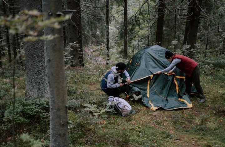
Tools and Materials Overview
Gather the essential gear: frame poles, canopy top, leg locks, weight bags, stakes, and a sturdy tarp. Follow the canopy tent instructions carefully, checking each component before assembly. Keep a tool kit handy—screwdriver, wrench, and a measuring tape to ensure a smooth setup. Solid tarp and windbreak panel completes kit quick.
Safety Precautions Before Setup
Before erecting your canopy, evaluate the site for uneven ground, hidden rocks, or debris that could damage the frame or cause injury. Clear a 20‑foot radius around the tent area, removing sharp objects, power lines, and low‑hanging branches that might interfere with the canopy’s height. Check the weather forecast; avoid setting up during high winds, heavy rain, or lightning storms. If wind speeds exceed 15 mph, postpone or use extra anchors. Read the manufacturer’s safety guidelines and ensure you understand all warnings. Wear sturdy footwear and gloves to protect your hands and feet from sharp edges. Keep a first‑aid kit nearby for minor cuts or scrapes. Verify that all components—poles, legs, and weights—are intact and free of damage before assembly. Test the lock mechanisms on the legs and corners to confirm they engage properly; feel for a secure click or snap. Have a helper on hand to assist with heavy components and keep the area clear of bystanders. Finally, confirm that the ground surface can support the weight of the tent and its anchors; avoid sandy or muddy spots that could shift. Use a level to ensure the frame is perfectly horizontal; a tilted canopy can cause uneven weight distribution and increase wind load. Inspect each pole for cracks, bends, or loose fittings before use; replace any compromised part immediately. Keep a fire extinguisher or water source nearby if the event is outdoors, especially in dry conditions. Label all straps and cords to avoid confusion during disassembly! Train staff on canopy handling when lifting or lowering the top. After setting up, perform a walk‑around to verify that all locks are engaged, stakes are secure, and the canopy is free of tension points!
Unboxing and Component Check
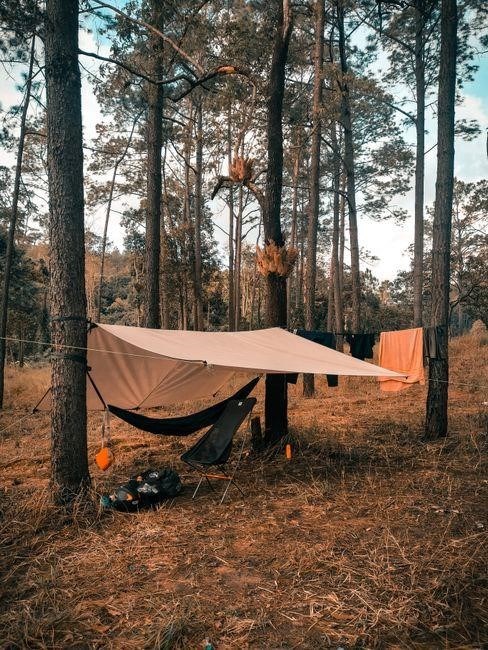
Begin by opening the canopy tent box with care, ensuring no sharp edges cut your hands. Lay out all parts on a flat surface and compare them to the manufacturer’s parts list: frame poles, adjustable legs, canopy top, weight bags, stakes, and optional wind‑break panels. Confirm that each pole has the correct length markings and that the locking tabs are intact. Inspect the canopy fabric for tears, missing seams, or color inconsistencies; any defect should be reported immediately.
Check that the leg locks click securely and that the quick‑release buttons function smoothly. Verify that the weight bags are sealed and that the stakes have sturdy tips. If the kit includes a wind‑break panel, ensure it folds flat and the straps are not frayed. Use a flashlight to examine hidden seams and fasteners for loose screws or broken clips. Document any missing or damaged items with photos and contact customer support before proceeding. Once all components are verified, store the packaging material in a dry, cool area to avoid moisture damage.
- Frame poles: length, color, and locking tabs.
- Legs: adjustable range, lock mechanism, and weight capacity.
- Canopy top: fabric integrity, seam quality, and color match.
- Weight bags: seal integrity and capacity rating.
- Stakes: tip durability and included anchor bags.
- Wind‑break panel: folding capability and strap condition.
Following this comprehensive unboxing checklist ensures that the canopy tent instructions are applied correctly, reducing the risk of assembly errors and enhancing overall safety.
Label each strap and cord with a unique identifier to avoid confusion during assembly and disassembly. Check that all fasteners—bolts, screws, and clips—are present and in good condition. If any component is missing, replace it with a genuine part from the manufacturer’s catalog. Keep a spare set of bolts or screws on hand for future maintenance. Finally, perform a quick visual inspection of the entire kit to ensure no parts are bent or warped, which could compromise structural integrity.
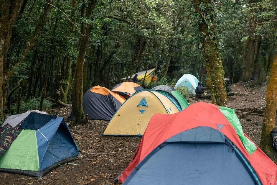
Measure each pole with a tape measure to confirm it matches the specified length on the parts list. Inspect the metal for signs of corrosion or rust, especially on the joints; any discoloration may indicate compromised strength. Test the tension of the adjustable legs by pulling them to their maximum extension and noting any looseness. Verify that the canopy top’s grommets are intact and that the fabric is free of lint or debris that could affect airflow. Ensure that the weight bags’ valves are functional by gently squeezing them to confirm they hold air. If any part fails these checks, replace it before proceeding.
All checks complete, you are ready to begin assembly per the canopy tent instructions.
Step 1: Assemble the Frame
Begin by placing the central pole upright on a level surface. Align the top of the pole with the designated height marker and secure it with the quick‑release clamp. Next, attach the side poles to the central pole using the provided locking brackets; each bracket should click firmly into place, indicating a secure connection. Slide the adjustable legs into the corresponding sockets, then lock them by pulling the lever until the audible click confirms engagement. Verify that all joints are tight by gently tugging each pole; any give signals a loose lock that must be re‑tightened. Use the included tension rods to maintain uniform pressure across the frame, ensuring the canopy stays taut. Finally, double‑check the frame’s symmetry by measuring the distance between opposite corners; they should match within a half‑inch tolerance. This step completes the skeleton that will support the canopy top, as outlined in the canopy tent instructions. When connecting the side poles, ensure each joint is fully seated before locking to avoid wobble. The locking mechanism typically features a spring‑loaded lever; press it firmly until you hear a distinct click. After all poles are locked, inspect the frame for any loose connections that might shift during use. A stable frame is critical for the canopy’s longevity and safety. If your model includes a quick‑release system, practice releasing and re‑locking a joint to become familiar with the feel and resistance. This helps prevent accidental releases during windy conditions. When the frame is fully assembled, perform a quick stability test by gently rocking the canopy; it should remain firm without shifting. This final check ensures the canopy is ready for reliable use! today!!

Step 2: Attach the Canopy Top
First, lay the canopy fabric over the assembled frame, ensuring the seams align with the designated attachment points. Slide the fabric into the top rail or hook system, depending on your model’s design. For most canopy tents, the top rail has four adjustable brackets that slide into the fabric’s corners. Align each corner with the corresponding bracket and push until the bracket’s locking clip engages. Once all four corners are secured, check that the fabric is evenly tensioned across the width; a sagging section indicates a loose corner or an improperly seated bracket. If the canopy has a central support pole, insert it through the fabric’s center opening and lock it into place using the spring‑loaded mechanism. This adds vertical stability and reduces the risk of the canopy lifting in moderate wind. Next, attach the tension straps that run from the frame’s base to the canopy’s corners. Pull each strap taut and fasten it to the designated anchor points on the frame. The straps should be snug but not overly tight, allowing the fabric to maintain a slight give for wind flow. Finally, inspect the entire canopy for any loose threads or exposed seams. A well‑secured canopy top not only looks professional but also ensures safety during windy conditions. Always refer to the canopy tent instructions for the number of straps locking mechanism. Ensure each strap is evenly distributed to prevent sagging; a balanced load keeps the canopy level and reduces strain on the frame during gusty conditions, enhancing overall durability and protection. Remember to double‑check all locks before finalizing setup to ensure maximum stability.
Step 3: Secure Leg Locks
After the canopy top is firmly attached, focus on the leg locks that anchor the frame to the ground. Most canopy tents feature a release latch on each leg that slides into a corresponding socket on the base plate. Slide the lock into the socket until you hear a satisfying click, indicating a secure connection. Repeat this process for all four legs, ensuring each lock is fully engaged. If the lock feels loose, gently pull the leg upward and re‑insert the latch; a seated lock should resist any force applied to the leg. In windy conditions, double‑check that the tension straps are still taut and that the leg locks have not shifted. The canopy tent instructions recommend inspecting each lock before finalizing the setup, as a single misaligned lock can compromise the entire structure. For added stability, attach weight bags or sandbags to the base of each leg. The mass counters the upward lift caused by wind and helps keep the frame level. If your model includes a locking mechanism that allows for release, test it by gently pulling the leg away from the base plate; the lock should disengage, confirming that it is not jammed. Once all locks are verified, perform a final walk‑around to ensure no leg is tilted or uneven. A well‑secured leg lock system not only provides safety but also extends the lifespan of the canopy by preventing undue stress on the frame joints. Remember, the key to a stable canopy is a combination of engaged leg locks, balanced weight distribution, and adherence to the canopy tent instructions for each specific model!XXXXXXXXXXXXXXXXXXXXXXXXXXXXXXXXXXXXXXXXXXXXXXXXXXXXXXXXXXXXXXXXXXXXXXXXXXXXXXXXXXXXXXXXXXXXXXXXXXXXXXXXXXXXXXXXXXXXXXXXXXXXXXXXXXXXXXXXXXXXXXXXXXXXXXXXXXXXXXXXXXXXXXXXXXXXXXXXXXXXXXXXXXXXXXXXXXXXXXXXXXXXXXXXXXXXXXXXXXXXXXXXXXX
Step 4: Add Weights and Anchors
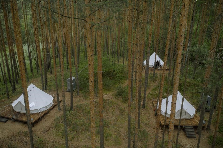
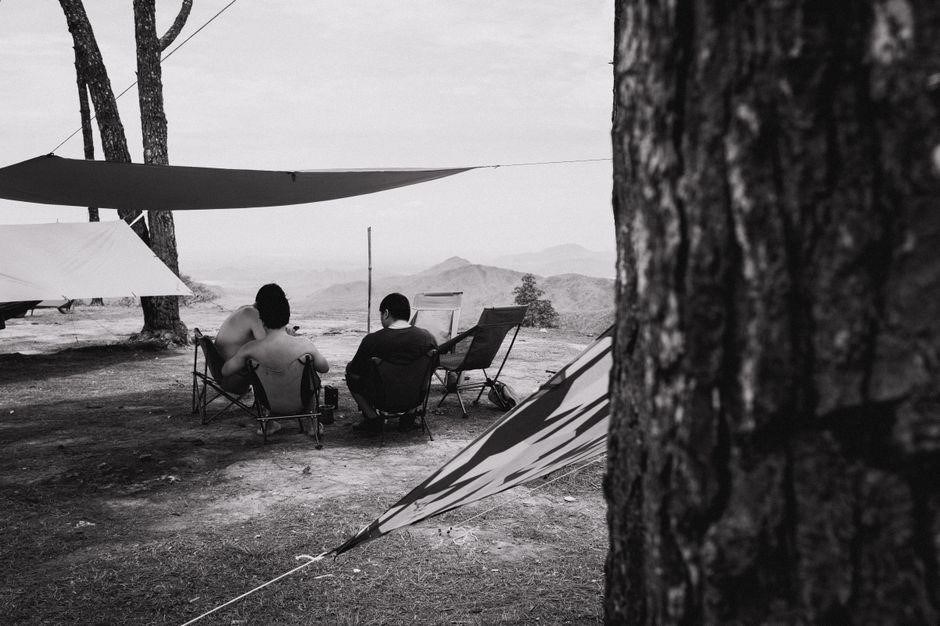
Secure the canopy by placing weight bags on each leg and anchoring stakes into the ground. Follow the canopy tent instructions: insert stakes through the designated holes, tighten with a lever, and attach weight bags to the base. Ensure all anchors are snug and evenly distributed. Secure all stakes firmly to avoid accident lift.

Stability and Wind Resistance Tips
When setting up a canopy, wind resistance is critical. First, choose a flat, firm ground to minimize shifting. Use stakes and anchor bags as described in the canopy tent instructions. Position stakes at each corner, driving them 12–18 inches into the soil. Attach anchor bags to the stakes, adding weight and preventing lift. Ensure the canopy top is fully tensioned; tighten all leg locks and sliders until they click firmly. Check the wind direction before finalizing the setup. If wind is coming from the front, orient the canopy so that the open side faces away, reducing drag. Use a windbreak panel or tarp on the windward side to further shield the structure. Locking mechanisms should be engaged on all joints; test by gently pulling each leg. Quick release features are handy for emergencies; keep them accessible but secure. Finally, monitor the canopy during the event; if wind speeds increase, add extra stakes or weights to maintain stability.
- Use a windbreak tarp on the windward side to reduce drag and protect the canopy from gusts.
- Check the tension of all leg locks; a loose lock can cause the canopy to tilt and lose stability.
- During high winds, add extra stakes or weight bags to counteract lift and keep the structure grounded.
Remember to inspect the canopy for any signs of wear before each use. Tighten all screws and bolts, replace any damaged parts immediately. In extreme weather, consider temporarily covering the canopy with a waterproof tarp to protect it from rain or snow. Keep the area clear of debris ensure that the canopy does not interfere with nearby structures or traffic and.!!!
Choosing the Right Ground Surface
Choosing the right ground surface is essential for a secure canopy setup. Start by surveying the area to identify flat, firm terrain free of rocks, roots, or loose soil. A compacted gravel or packed dirt base offers the best support, preventing the frame from sinking or shifting during use. Avoid sandy or muddy spots, as they can cause instability and make stakes difficult to drive. If the natural ground is uneven, level it with a board or a lightweight tarp, then add a layer of sand or small pebbles to create a stable foundation. This layer should be at least 4–6 inches thick to distribute weight evenly. For temporary events, consider using a pre‑made ground mat or a canvas groundsheet; these provide a smooth surface and protect the canopy from punctures. Always check the moisture level; wet ground can soften and collapse under the canopy’s weight, so allow it to dry or use a drainage mat if necessary. When the surface is prepared, place the canopy frame on it and secure the legs with stakes or anchor bags, following the canopy tent instructions for optimal placement. A well‑chosen ground surface ensures that the canopy remains upright, reduces the risk of damage, and provides a comfortable, safe environment for guests and equipment alike.
When the canopy is in place, double‑check that the ground beneath remains level. A slight slope can cause uneven weight distribution, leading to wobble. If you’re on a grassy patch, roll a small board across the area before staking. For sandy sites, spread a layer of sandbags or a thick tarp to hold the frame steady. keep the ground clean of debris, as loose objects can shift under the weight and compromise stability.
Using Stakes and Anchor Bags Effectively
Stakes and anchor bags are the backbone of a stable canopy. Begin by selecting stakes that match the ground type: metal or wooden stakes for hard surfaces, plastic for soft soil. Drive each stake at least 12 inches into the ground, angling it slightly outward to resist pull. Attach the anchor bag to the stake’s eye, ensuring the bag’s weight is evenly distributed across the canopy’s lower frame. Follow the canopy tent instructions: first secure the legs, then insert the stakes, and finally add the anchor bags.
For windy conditions, double‑stake by placing a secondary stake 6 inches from the first, and use a weighted anchor bag that contains sand or gravel. When using multiple anchor bags, stagger them around the perimeter to balance the load. Check each lock and clip for a firm click before tightening the stakes. If the ground is uneven, use a groundsheet or tarp to create a level base; this prevents the stakes from slipping. After all stakes are in place, test the canopy by gently pulling on the frame; any movement indicates a need for additional anchoring.
Finally, secure the canopy’s corners with the built‑in locking mechanism, then perform a wind check. Proper use of stakes and anchor bags not only stabilizes the structure but also extends its lifespan by preventing stress on the frame and fabric. Remember to rotate anchor bags periodically if the event lasts several hours, as sand can shift and reduce weight. For large events, consider using weighted anchor bags that hold 20–30 pounds each, and place them at least four points around the frame. Always keep a spare stake and bag on hand in case of damage or sudden weather changes.
Locking Mechanisms and Quick Release Features
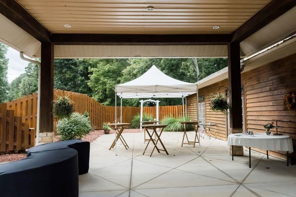
Use the built‑in locking pins to secure each joint; they click firmly into place. Quick‑release levers allow rapid disassembly—pull the lever, the pin pops, and the frame collapses in seconds; Follow the canopy tent instructions to engage locks before adding weight or stakes.
Check lock engagement before final setup now .
Common Setup Mistakes to Avoid
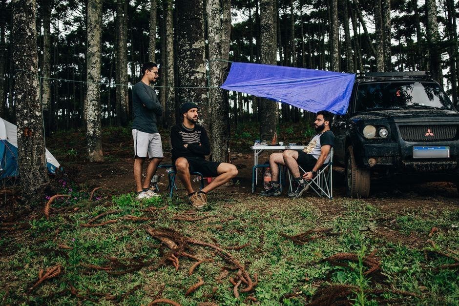
A final reminder: always check the canopy tent instructions for any nuances. For example, some designs feature a quick‑release mechanism that requires a lock lever, while others use a simple twist‑lock. Misreading these details can lead to a weak frame that may buckle under load. Additionally, never assume that a single stake is enough for a large canopy; distribute weight evenly across all anchor points. Wind test blowing across canopy to ensure it holds firm before guests arrive.
Overlooking Manufacturer Specific Instructions
When setting up a canopy tent, it is essential to consult the manufacturer’s specific instructions before proceeding. Many users overlook critical details such as the order of assembly, the proper placement of leg locks, and the recommended weight distribution for each model. Failure to follow these guidelines can result in a compromised structure, increased risk of collapse, and potential damage to the canopy fabric. Manufacturers often provide diagrams that illustrate the correct orientation of the frame, the sequence for attaching the canopy top, and the exact points where anchor weights should be placed. Ignoring these diagrams may lead to uneven tension across the canopy, causing sagging or wind‑induced ripples that weaken the overall integrity of the tent. Additionally, some manufacturers include safety warnings about the maximum load capacity of the frame and the recommended types of stakes or anchor bags. Overlooking these warnings can expose the tent to excessive stress during high‑wind conditions, potentially causing the frame to bend or the canopy to tear. Finally, many manufacturers offer optional accessories—such as UV‑protective coatings, rain covers, or ventilation panels—that can enhance performance if used correctly. Skipping the installation of these accessories may reduce the tent’s durability and comfort. Therefore, always read the manufacturer’s specific instructions thoroughly, follow the recommended steps, and double‑check every component before finalizing the setup. This diligence ensures a safe, stable, and long‑lasting canopy tent experience.
- Check frame
- Verify anchor
- Add weight