The JS Bull eBike Controller‚ manufactured by Jiangsu Wuxi Bull Technology Co․‚ Ltd․‚ is a high-performance brushless motor controller designed for electric bikes․ It efficiently manages power distribution‚ ensuring optimal motor operation and reliability․ Popular among enthusiasts‚ it supports advanced customization‚ including phase angle and current limit adjustments‚ making it suitable for high-power eBike setups like the 84V 3000W model․
1․1 Overview of the JS Bull Controller
The JS Bull Controller is a high-performance brushless motor controller designed for electric bikes․ It supports 60° and 120° phase angles‚ with a current limit range of 10A to 80A‚ making it suitable for various eBike setups․ Compatible with 36V‚ 48V‚ 52V‚ and 84V battery systems‚ it ensures reliable power management and customizable settings for optimal eBike performance․
1․2 Importance of the Controller in eBike Functionality
The JS Bull Controller acts as the central nervous system of an eBike‚ managing power flow from the battery to the motor; It ensures efficient energy distribution‚ enabling smooth acceleration and maintaining optimal performance․ By regulating current and phase angles‚ it prevents overheating and damage‚ making it essential for safe and reliable eBike operation․ Proper settings enhance both power and durability․

Key Features of the JS Bull Controller
The JS Bull Controller offers high voltage and current capabilities‚ supporting up to 84V and 80A․ It features adjustable phase angles (60°/120°) and multiple operating modes‚ ensuring versatility for various eBike setups․ The controller also includes a detailed wiring manual for safe and efficient power management․
2․1 Voltage and Current Specifications
The JS Bull Controller supports a maximum voltage of 84V and a current limit of 80A‚ catering to high-power eBike systems․ It is compatible with various battery voltages‚ including 36V‚ 48V‚ and 52V configurations‚ ensuring flexibility for different setups․ This range allows riders to achieve optimal performance and efficiency across diverse terrains and conditions․
2․2 Motor Phase Angle and Operating Modes
The JS Bull Controller offers adjustable motor phase angles of 60° and 120°‚ enhancing efficiency and torque delivery․ It features three operating modes‚ allowing riders to customize performance based on terrain and preference‚ ensuring optimal power utilization and a tailored eBike experience․
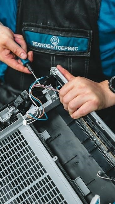
2․3 Wiring Manual and Power Management
The JS Bull Controller includes a detailed wiring manual to ensure safe and proper connections․ It supports various power management features‚ including adjustable current limits and battery voltage settings (36V/48V/52V)‚ to optimize performance and prevent overloading․ Proper wiring and configuration are crucial for maximizing efficiency and ensuring reliable operation of the eBike system․

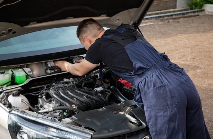
Installation and Setup Guide
Installing the JS Bull Controller requires careful alignment with your eBike’s motor and battery․ Ensure compatibility with your motor type and follow the wiring manual precisely․ Proper tools and safety precautions‚ such as disconnecting the battery‚ are essential․ Technical knowledge is recommended for a smooth setup‚ and professional assistance may be needed for complex configurations․
3․1 Compatibility with Different eBike Motors
The JS Bull Controller is compatible with various eBike motors‚ including brushed and brushless types‚ operating within specified voltage and current limits․ It supports motors with phase angles of 60° or 120°‚ ensuring versatility․ Compatibility checks are essential to match the controller’s specifications with the motor’s requirements for optimal performance and to avoid potential operational issues․
3․2 Step-by-Step Installation Process
Begin by disconnecting the battery to ensure safety․ Connect the motor and phase wires to the controller‚ followed by the sensor wires․ Next‚ link the power lines to the battery and other components․ Secure all connections firmly and reconnect the battery․ Finally‚ test the system at low power to verify proper operation before full use․
3․3 Troubleshooting Common Installation Issues
Common issues include error codes‚ no power output‚ or wiring problems․ Check connections for loose wires and ensure proper phase and sensor alignment․ Verify battery voltage matches the controller’s specifications․ Consult the manual or online guides for error code meanings․ Test the system at low power to identify faults before full operation․

Parameter Settings and Configuration
The JS Bull controller allows adjusting current limits‚ phase angle‚ and voltage settings via programming tools․ Proper configuration ensures optimal performance and safety‚ following the manual guidelines․
4․1 Adjusting Current Limits and Phase Angle
Adjusting current limits on the JS Bull controller ensures optimal motor performance and prevents overheating․ The phase angle can be set between 60° and 120°‚ depending on the motor type and desired efficiency․ Proper configuration requires consulting the manual and using compatible software tools to avoid damage and ensure safety․
4․2 Configuring Battery Voltage and Mode Settings
Configuring the JS Bull controller involves setting the battery voltage to match your eBike’s specifications‚ such as 36V‚ 48V‚ or 52V․ Operating modes can be adjusted to optimize performance‚ with options like Eco‚ Sport‚ or Turbo․ Proper configuration ensures efficient power delivery and prevents damage․ Always refer to the manual or use compatible software tools for precise adjustments․
4․3 Customizing Settings for Optimal Performance
Customize the JS Bull controller by adjusting phase angles (60° or 120°) and current limits (10A-80A) to suit your riding style․ Utilize the controller’s three operating modes to balance speed and efficiency․ Advanced users can fine-tune parameters using software tools for enhanced performance‚ ensuring optimal power delivery and adaptability to various terrains or riding conditions․

Safety Features and Precautions
The JS Bull controller features built-in safety mechanisms‚ including overcurrent protection and thermal monitoring․ Proper handling and maintenance are essential to prevent damage and ensure reliable operation․
5․1 Built-In Safety Mechanisms
The JS Bull controller incorporates multiple safety features‚ including overcurrent protection‚ thermal monitoring‚ and voltage regulation․ These mechanisms prevent overheating‚ short circuits‚ and battery over-discharge‚ ensuring safe and reliable operation․ Fault detection systems automatically disconnect power in case of anomalies‚ safeguarding both the controller and the eBike’s electrical components from potential damage․
5․2 Handling and Maintenance Best Practices
Regularly inspect the controller for signs of wear or damage․ Clean connectors to prevent corrosion and ensure proper connections․ Avoid exposure to water or extreme temperatures․ Use appropriate tools for adjustments to prevent damage․ Store the controller in a dry‚ cool place when not in use to maintain optimal performance and longevity․
5․3 Avoiding Common Mistakes
Avoid incorrect wiring connections‚ as they can damage the controller or cause safety hazards․ Do not exceed the recommended voltage or current limits․ Ensure proper cooling and ventilation to prevent overheating․ Regularly update firmware to maintain optimal performance․ Always follow the manufacturer’s guidelines for parameter settings and avoid overloading the system․ Properly secure all connectors to prevent loose connections during operation․
Advanced Customization and Modifications
Enhance performance by upgrading firmware‚ adjusting parameters‚ and installing additional features․ Explore advanced tuning options to optimize motor efficiency and tailor the controller to your riding preferences․
6․1 Upgrading Firmware for Enhanced Performance
Upgrading the JS Bull controller’s firmware enhances performance by improving efficiency‚ stability‚ and compatibility․ Download the latest firmware from trusted sources and use a compatible programming tool․ Follow step-by-step instructions to flash the firmware‚ ensuring all settings like phase angle and current limits are correctly configured․ This update optimizes motor operation and supports advanced customization for better ride quality and reliability․
6․2 Installing Additional Features
Installing additional features on the JS Bull controller enhances functionality․ Options include regenerative braking‚ customizable display settings‚ and temperature monitoring․ Ensure compatibility with your eBike’s motor and battery before installation․ Follow detailed manufacturer guidelines to integrate new features without compromising performance․ Regularly update firmware to support new additions and maintain optimal operation․
6․3 Advanced Tuning and Parameter Optimization
Advanced tuning of the JS Bull controller involves adjusting phase angles‚ current limits‚ and voltage settings for optimal performance․ Fine-tune acceleration and torque by modifying motor phase angles between 60° and 120°․ Adjust current limits to prevent overheating and maximize efficiency․ Use specialized tools to customize settings‚ ensuring they match your eBike’s motor and battery specifications for enhanced reliability and power delivery․

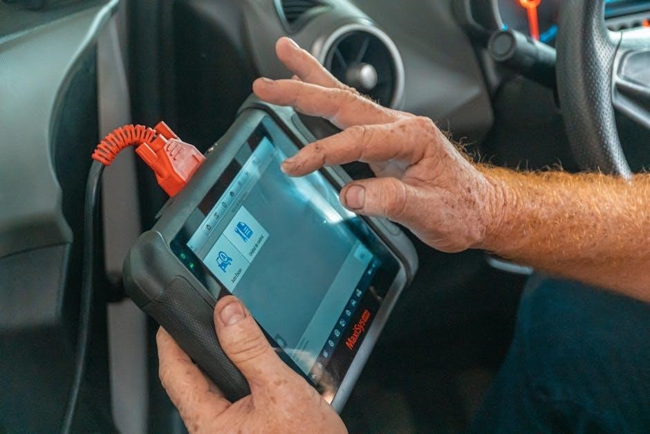
Troubleshooting Common Issues
Common issues include power cut-offs‚ communication errors‚ and motor or battery disconnections․ Check wiring connections‚ battery voltage‚ and phase angles․ Ensure settings match motor specs for reliable operation and to prevent overheating․ Refer to the manual for diagnostic steps and solutions to restore functionality quickly and safely․
7․1 Diagnosing Power Issues
Diagnosing power issues involves checking battery voltage‚ wiring connections‚ and phase angle settings․ Ensure the controller is compatible with your motor and battery specifications․ Verify that current limits are set correctly to avoid cut-offs․ Inspect connectors for damage or corrosion and ensure proper installation․ Refer to the manual for specific troubleshooting steps to identify and resolve power-related problems effectively․
7․2 Resolving Communication Errors
Communication errors often occur due to faulty connections or software glitches․ Check all wiring between the controller‚ motor‚ and display․ Ensure secure connections and inspect for damage․ Restart the system or update firmware to resolve software issues․ If errors persist‚ refer to the JS Bull manual for detailed troubleshooting steps or contact technical support for assistance․
7․3 Fixing Motor and Battery Connectivity Problems
Motor and battery connectivity issues often arise from loose or corroded connections․ Inspect and clean all terminals‚ ensuring proper tightness․ Verify that the phase wires are correctly matched to the motor․ Check the battery voltage and balance․ Consult the JS Bull manual for wiring diagrams and troubleshooting guides to resolve connectivity problems effectively․ Always ensure components are compatible․

Maintenance and Upkeep
Regular maintenance ensures optimal performance and longevity․ Clean connectors‚ inspect wiring‚ and update firmware․ Store the controller in a dry‚ cool place to prevent damage․
8․1 Routine Checks and Cleaning
Perform routine checks to ensure all connections are secure and free from corrosion․ Clean the controller’s exterior and internal components gently with a soft cloth and non-conductive cleaner․ Regularly inspect wiring for signs of wear or damage to prevent power issues․ Maintain a dry environment to avoid moisture-related malfunctions and ensure reliable operation․
8․2 Updating Software and Firmware
Regularly check for and install software and firmware updates for the JS Bull eBike Controller․ Follow the manufacturer’s instructions to ensure a smooth update process․ Keep the eBike connected to a power source during updates to avoid interruptions․ Updates enhance performance‚ add new features‚ and maintain system compatibility and stability․
8․3 Storage and Transportation Tips
Store the JS Bull eBike Controller in a cool‚ dry place‚ away from direct sunlight and moisture․ Disconnect the battery to prevent power drain․ When transporting‚ secure the controller in protective packaging to avoid physical damage․ Avoid exposing it to extreme temperatures or shocks․ Proper handling ensures long-term reliability and performance of the controller during storage and transit․
The JS Bull eBike Controller is a vital component‚ ensuring efficient power management and reliability․ Proper setup‚ maintenance‚ and adherence to guidelines are essential for optimal performance and safety․
9․1 Summary of Key Points
The JS Bull eBike Controller is a high-performance brushless motor controller designed for efficient power management․ It supports advanced customization‚ such as phase angle and current limit adjustments․ Proper installation‚ configuration‚ and maintenance are crucial for optimal functionality and safety․ Adhering to the manual ensures reliable operation and maximizes the controller’s potential for enhanced eBike performance․
9․2 Final Tips for Optimal Controller Performance
Regularly update firmware for enhanced features and bug fixes․ Ensure proper wiring and connections to avoid power issues․ Adjust current limits and phase angles according to your motor specifications․ Monitor temperature during operation to prevent overheating․ Always follow the manual guidelines for customization and maintenance to ensure longevity and peak performance of the JS Bull controller․
9․3 Importance of Following the Manual
Adhering to the JS Bull eBike controller manual ensures safe installation‚ configuration‚ and operation․ Proper steps prevent damage to components‚ optimize performance‚ and maintain warranty validity․ Incorrect settings can lead to malfunctions or safety hazards‚ emphasizing the manual’s role in guiding users for reliable and efficient eBike functionality․ Always refer to it for troubleshooting and maintenance․